The efficiency of a power supply depends not only on the selected product or system, but also on the supply concept and therefore on the configuration. This applies to both new installations and repowering measures, i.e. when replacing existing systems with newer ones.
How can efficiency be increased and which supply concepts are the best?
Clarification of terms
Redundancy: Redundancy is understood to mean the presence of more operational technical resources than are necessary to fulfill the intended function*. This means having one more system or component available than is actually necessary. This means that if a component fails, the system function is maintained. * Source: Büdenbender, Ulrich / Heintschel von Heinegg, Wolff / Rosin, Peter: Energierecht I - Recht der Energieanlagen, New York 1999.
Supply concepts: In principle, the power supply concepts can be implemented with one or two paths:
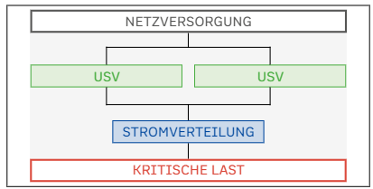
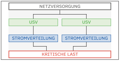
Figure 1 Classic supply system with a mains supply, a load and a UPS in between, which is designed either as a single or redundant configuration.Figure 2: With two paths, two UPS systems are used with separate sub-distribution boards and separate power supplies (e.g. necessary with two separate fire compartments)
UPS redundancy concepts
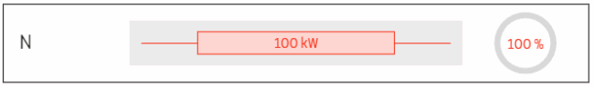
Example: 100kW load with one path
Case 1: Single system, 100 % loadable (without redundancy) → If the system fails, a reliable power supply is no longer available.
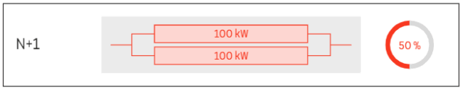
Case 2: N+1 with 2x 100kW in parallel, each system 50 % loadable → Common practice: The UPS power is doubled for the purpose of redundancy. With a load of over 50 %, one system could not take over the load if the second system fails.
Case 3: N+1 with 3x 50kW in parallel, each system 67 % loadable → In this case, the N+1 configuration is not implemented by doubling the power, but with smaller power components (modules) with 50 kW each. One module is therefore available for redundancy. Each system/each module can be loaded more heavily so that the UPS systems are operated more efficiently in this case. This case is predestined for plug-in modular systems. The configuration could also be realized with block UPS systems, but only with much higher infrastructure costs in terms of bypasses, power supplies and battery systems.
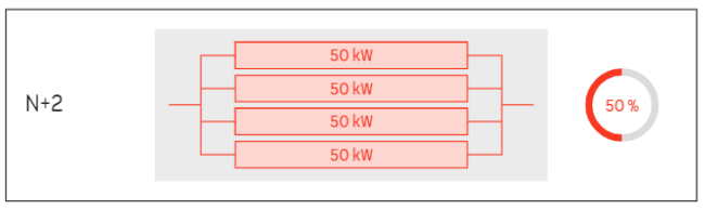
Case 4: N+2 with 4x 50kW in parallel, each system 50 % loadable → The configuration from case 3 can be extended as required by an additional 50kW module (N+2, N+3, ...). Although this increases the redundancy, the result is that the modules are again less loaded, making the configuration less efficient.
Example: 100kW load with two paths
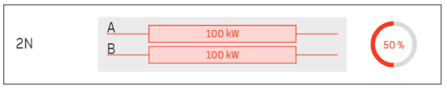
Case 1: Two paths (A+B), 2x 100kW in parallel, each system 50 % loadable → In this so-called 2N configuration, two systems are operated independently of each other in parallel. The load of one system is 50 %.
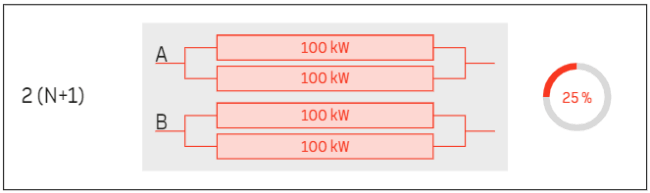
Case 2: Two paths, 2x 100kW each in parallel, each system 25 % loadable → The UPS power was doubled in each path so that two systems with 100kW each are available per path, resulting in a total power of 400kW. This results in an even lower load on the individual systems, meaning that this configuration is not worth striving for.
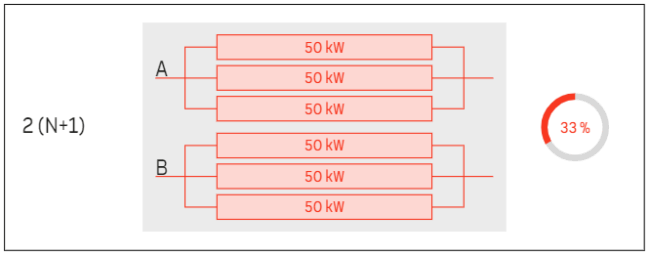
Case 3: Two paths, 3x 50kW each in parallel, each system 33 % loadable → Redundancy was created for each path using smaller power modules. The total output is now only 300 kW, meaning that the systems are better utilized and therefore more efficient in operation.
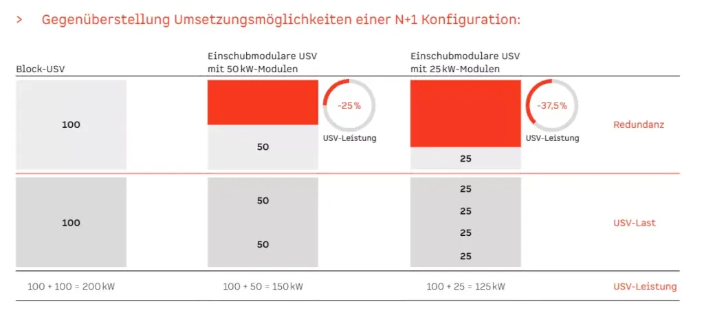
Increased efficiency through slide-in modular systems
If an N+1 configuration is implemented with a block UPS system, this results in a total output of 200kW using the example of a 100kW load - made up of a 100kW load and 100kW redundancy. If, on the other hand, a plug-in modular UPS system with 50kW modules is used, the required output of 100kW is covered by two modules and only one additional module and therefore only 50kW is required as redundancy. This results in a total output of 150kW. An N+1 configuration with 25kW modules results in a total output of only 125kW, which equates to a saving of 37.5 % compared to the block UPS system.
Savings potential
While block UPS systems typically have efficiencies of less than 90 % at loads of over 50 %, withdrawable UPS systems from Wöhrle achieve efficiencies of 96 % and higher even at low loads:
A potential saving of 2% sounds small, but when you take a closer look, it makes a big difference in terms of power consumption, energy costs and CO₂ emissions. Take a look at our white paper "UPS repowering is climate protection" and find out how improving efficiency can lead to savings of several thousand euros per year.
Further increase in efficiency through "performance virtualization"
Our UPS modules have a Hibernation mode. The UPS modules can be set so that they switch automatically every 14 days, for example, and are in sleep mode for this time. The module's inverter is not active during this time, but the module switches on automatically when required. The advantage of this is not only the increase in efficiency, but also the protection of the components, as wearing parts such as capacitors are protected during this time
Hot-swap capability
Individual modules can also be replaced during operation without shutting down the system or switching to the bypass. This provides an enormous advantage for service and maintenance work and means that this can be carried out quickly and efficiently without compromising the security of supply to the load during this period.
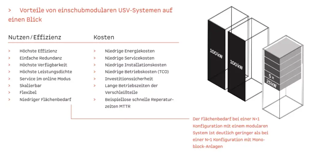
Advantages of rack-mounted UPS systems at a glance